Frequently Asked Questions
Firestopping issues can be complex and are often fact specific. IFC does not warrant that the advice given will accurately fit your situation. Suitability of advice or recommendations must be determined by the user.
CHOOSE A TOPIC TO SEE RELATED QUESTIONS & ANSWERS
The list of special inspectors published by the International Firestop Council is a listing of those individuals (not companies) who have completed the “IFC recommended Training and Education for Third-Party Firestop Inspectors” program, and have passed the proctored end-of-study exam. This program is formally recognized as providing suitable and sufficient firestop knowledge by
- ICC-ES standard AC291,
- ASTM standard E3038,
- The HCAI (formerly OSHPD) government agency in California
- The Unified Facilities Guide Specifications (UFGS), issued by the US Federal government, for construction at US military bases and by NASA
- The UAE Building Code,
- As well as by countless US jurisdictions in which special inspectors are being required for firestopping.
The individuals in the IFC list do not pay any fee to be listed there. They only need to have passed the examination. They do not need to purchase an IFC membership to be listed there. The IFC encourages property owners and AHJs to make use of the IFC list in determining if a proposed special inspector has suitable qualifications for firestopping inspection.
According to the FCIA website, the companies that are in its published list are companies who have purchased a 1-year FCIA membership for $625 or more. As we understand, there is no requirement for any of the employees or management of those companies to possess any measurable or recognizable qualifications in firestop special inspection. The FCIA list is that of a membership program, not a qualifications assessment program.
Yes. Special inspection of projects for the US Army, Navy, Air Force, and NASA are specified in the Unified Facilities Guide Specifications (UFGS). This collection of documents is a joint effort of the U.S. Army Corps of Engineers (USACE), the Naval Facilities Engineering Systems Command (NAVFAC), and the Air Force Civil Engineer Center (HQ AFCEC). The UFGS document on special inspection can be found at https://www.wbdg.org/FFC/DOD/UFGS/UFGS%2001%2045%2035.pdf . Section 1.5.15.1 explicitly recognizes the IFC Special Inspector exam as being an acceptable examination credential for firestop special inspection.
Some assemblies are specified in design documents or in building code as needing to restrict/limit the leakage of smoke, even when the wall or floor assemblies do not require a fire resistance rating. Examples of such assemblies are “smoke partitions”, as specified in IBC (2018) section 710, or assemblies in the National
Building Code of Canada that are “Fire Separations” that do not require a fire resistance rating. Some people refer to such assemblies as “zero-rated assemblies” or “smoke walls”, although neither of those terms is actually used in any code or standard, and thus have no established meaning.
There is no standard procedure available for how to inspect seals of penetrations or joints in non-fire-rated assemblies. ASTM E2174 and E2393 are based on the premise that each penetration or joint inspected can be compared to a design document that objectively indicates what the correct sealing method is in order to provide the desired fire resistance rating. Those design documents are specified in the ASTM standards as being systems that are tested to the relevant fire test standards, or else judgments (often called Engineering Judgments) that should be careful extrapolations or interpolations of systems tested to the relevant fire test standards.
Installation details that are not based on any published fire test standard (or resultant EJ) could not be included as part of an inspection to ASTM E2174 or E2393.
For penetrations, the tested systems would have been evaluated per fire test methods ASTM E814, UL1479, CAN/ULC-S115, EN1366-3, EN 13665, or ISO 10295-1. For fire resistive joint systems, the tested systems would have been evaluated per fire test methods ASTM E1966, UL2079, CAN/ULC-S115, EN1366-4, ISO 10295-2, or BS 476 Part 20. For perimeter fire containment systems (curtain wall edge-of-slab joints), the tested systems would have been evaluated per fire test methods ASTM E2307 or EN 1366-4. And for Continuity Head-of-Wall Joints (i.e. rated wall to nonrated floor/roof intersections), the tested systems would have been evaluated per fire test method ASTM E2837.
Engineering judgments (EJs) that have been Approved by the Authority Having Jurisdiction might also be provided as design documents against which to evaluate installations being inspected to ASTM E2174 or E2393. Per IFC Guidelines for the Evaluation of Engineering Judgments, all EJs would need to be based on the assumption and declaration that the proposed design would be expected to pass one of the aforementioned fire tests to provide the indicated rating, if it were to be tested.
Since there is no published test method for evaluating smoke seals for penetrations or joints that might be installed within walls or floors that are not required to have a fire resistance rating, there is no objective document against which to compare a field installation. Thus, an objective inspection with a conclusion of “acceptable” or “unacceptable” is not possible within the context of E2174 and E2393. Someone can decide that they are going to inspect some installed smoke seals, for example for QA/QC purposes. However, such an inspection would never be within the scope of ASTM E2174 or E2393.
The M-rated firestop systems would not meet NFPA 13 requirements as it does not require the firestop system to be movement tested per the new ASTM standard. NFPA13 requires a “spongy” surrounding around the sprinkler pipe. Each firestop manufacturer typically has one or more systems that meet the NFPA 13 requirement. If you wanted to use an M-rated penetration firestop system instead of the prescriptive penetration seismic protection prescribed by NFPA 13, it would need to be submitted under the code allowance for “Alternate Materials and Methods” and be approved by the AHJ.
For movement applications other than the NFPA-required sprinkler pipe seismic protection, the new M-rating from UL simply provides another extra, optional performance measurement in case it’s something of interest to a property owner. This is similar to the W-rating for water leakage, mold resistance ratings per ASTM G21, and product VOC measurements to meet LEED requirements. None of these other firestop attributes are required by any code. But they could be of interest to a property owner looking for some firestop performance that goes beyond the code-mandated F and T ratings.
Yes, the IFC program is recognized by HCAI as providing suitable qualifications for inspection of firestopping. See the HCAI webpage information here: https://hcai.ca.gov/facilities/building-safety/resources/fire-life-safety-faqs/#11-what-training-for-special-inspection-agencies-and-special-inspectors-is-acceptable-for-special-inspections-of-fire-resistance-penetrations-and-joints.
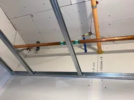
Unless the soffit being installed is in full accordance with a fire resistance rated floor-ceiling design, and provides the needed thermal (fire) protection of the floor-ceiling assembly, then for building code and fire protection purposes, it’s like the soffit does not even exist. It is an unrated assembly, and thus does not add any measurable and known fire protection to the floor-ceiling assembly. The “real” ceiling must provide 100% of the required fire protection.
If the ceiling drywall that you show in the photo is part of a fire resistance rated floor-ceiling assembly, then it must be installed in full accordance with the tested and listed design. You should take a look at the design (listing) document to see what is required for all of the butt joints. I have never seen a floor-ceiling assembly that does not require mud and tape of all of the butt joints.
Similarly, any penetration of the ceiling that is part of the fire resistance rated floor-ceiling assembly must be protected with a penetration firestop system installed as tested to ASTM E814/UL1479. Once again, the presence of a soffit below that does not waive any of the code requirements for firestopping.
IBC code requirements for penetration firestops, fire resistive joint systems, and perimeter fire barriers (aka curtain wall firestopping, perimeter gap firestopping, or edge-of-slab firestopping) never mandate that the acceptable solution needs to be listed by a listing laboratory. The code requirement in each case is for the firestopping to be “installed as tested”. In other words, you must have some test evidence that proves that what is being installed conforms to a fire-tested and rated solution. The IBC indicates what the required fire test is in each case:
Penetration firestops: ASTM E814 or UL 1479
Fire resistive joint systems: ASTM E1966 or UL 2079
Perimeter fire barriers: ASTM E2307
A convenient way to communicate trustworthy test results to designers, specifiers, installers and Authorities Having Jurisdiction is via system “listings”, which are published by various accredited test laboratories. In past decades, the systems were published in large books called “Directories”. Those systems are now found in online directories. The code does not mandate that the test result must be in the form of a listing, but having the required test result as a listing provides a guarantee that the test result is legitimate, provides the specific details of acceptable/conforming installations, specifies what test method was used, and clearly indicates what fire resistance rating was obtained.
So which test laboratories are trustworthy, and can be counted on to publish systems that AHJs and others should readily approve? The list of such reliable labs is decided by the US Occupational Safety and Health Administration (“OSHA”). They maintain a list of accredited laboratories that they term the “Nationally Recognized Test Laboratories” (NRTL). A list of those can be found at https://www.osha.gov/dts/otpca/nrtl/nrtllist.html . UL is a very well-known NRTL, Intertek has equal status as an NRTL. Another well-known NRTL is FM Approvals (previously known as “Factory Mutual”).
For curtain wall (edge-of-slab) firestopping, the majority of available system listings are in fact from Intertek. One main reason for that is that there were many years when UL was not performing any such fire testing (to ASTM E2307). Thus, for the firestopping of the joint between a curtain wall and a fire-rated floor slab, the majority of available tested and listed systems are from Intertek. Intertek does also list penetration firestop systems and fire-resistive joint systems. However, in those latter two categories of firestopping, 95%+ of available listings are published by UL.
A listing from Intertek is just as acceptable as the listing from any of the other NRTLs (UL, FM, etc). The important part of approving a proposed firestop system is to make sure that the actual field conditions match the listed system details precisely.
A firestop system that indicates a zero (0″) annular space as part of the range of acceptable annular space values is permitted to have a single point of contact between the penetrating item and the inside of the hole it is routed through. If the system specifically mentions that a “continuous point of contact” is allowable, then it is acceptable for the annular space to be 0” all the way around the penetrating item.
If you would like some additional information and explanation about firestop systems that include a point of contact, review this article published by IFC-member company, Specified Technologies (STI): https://www.stifirestop.com/news/just-bead-it-sealing-the-point-contact-location
Click here for more information
Premier Certificate Holders have an upgraded listing with their logo and contact information on the IFC website within the
Certificate Holders Page
There is no tested use for putty pads in ceiling membranes. UL doesn’t currently have a category for such protection to be listed. Note that UL listing category CLIV, which is where most putty pad listings are found, is for “wall opening protective materials,” not for ceilings.
There are very few companies that sell protective devices, measures, or solutions for openings in ceilings. This is why the recent IFC document, Guide for Protection of Recessed Boxes in Fire-rated Walls Using Firestop Putty Pads, Box Inserts, Cover Plate Gaskets and Endothermic Mats, covers only wall openings. To learn more about the topic of openings in ceiling membranes, see pages 70-75 and pages 174-183 of the ICC book on firestopping and dampers. None of the protection discussed there would allow or require putty pads for openings in a ceiling.
There are IBC protection requirements for gaps in ceilings of floor/ceiling and for roof/ceiling assemblies, but they do not involve putty pads. Ceilingsare challenging to protect and more critical than walls. Allowing a fire to get prematurely into a floor/ceiling or roof/ceiling assembly space can lead to premature collapse of the floor or roof. Wall firestopping errors will typically not lead to any localized or wider structural collapse, although inadequate firestopping in walls can likely lead to fire and smoke spread through the rated wall. The only allowable gaps, openings or other breaches in the ceiling of a floor/ceiling assembly or of a roof/ceiling assembly should be those that are explicitly described within the assembly listing, and provided with the protection methods as exactly described in that listing
703.7 Marking and identification. Where there is an accessible concealed floor, floor-ceiling or attic space, fire walls, fire barriers, fire partitions, smoke barriers and smoke partitions or any other wall required to have protected openings or penetrations shall be effectively and permanently identified with signs or stenciling in the concealed space. Such identification shall:
1. Be located within 15 feet (4572 mm) of the end of each wall and at intervals not exceeding 30 feet (9144 mm) measured horizontally along the wall or partition.
2. Include lettering not less than 3 inches (76 mm) in height with a minimum 3/8-inch (9.5 mm) stroke in a contrasting color incorporating the suggested wording, “FIRE AND/OR SMOKE BARRIER—PROTECT ALL OPENINGS,” or other wording.
Section 703 of the International Fire Code (IFC) contains the requirements for the maintenance of firestop systems in existing buildings. It states:
703.1 Maintaining protection. Materials and firestop systems used to protect membrane and through penetrations in fire-resistance-rated construction and construction installed to resist the passage of smoke shall be maintained. The materials and firestop systems shall be securely attached to or bonded to the construction being penetrated with no openings visible through or into the cavity of the construction. Where the system design number is known, the system shall be inspected to the listing criteria and manufacturer’s installation instructions.
Similarly, under the general section 701 of the IFC, it states:
701.5 Maintaining protection. Materials, systems and devices used to repair or protect breaches and openings in fire-resistance-rated construction and construction installed to resist the passage of smoke shall be maintained in accordance with Sections 703 through 707.
701.6 Owner’s responsibility. The owner shall maintain an inventory of all required fire-resistance-rated construction, construction installed to resist the passage of smoke and the construction included in Sections 703 through 707. Such construction shall be visually inspected by the owner annually and properly repaired, restored or replaced where damaged, altered, breached or penetrated. Records of inspections and repairs shall be maintained. Where concealed, such elements shall not be required to be visually inspected by the owner unless the concealed space is accessible by the removal or movement of a panel, access door, ceiling tile or similar movable entry to the space.
Having said that, the International Building Code (IBC) does not mandate 3rd party inspection in every instance. IBC section 1705 states the following:
1705.17 Fire-resistant penetrations and joints. In high-rise buildings or in buildings assigned to Risk Category III or IV, special inspections for through-penetrations, membrane penetration firestops, fire-resistant joint systems and perimeter fire barrier systems that are tested and listed in accordance with Sections 714.4.1.2, 714.5.1.2, 715.3 and 715.4 shall be in accordance with Section 1705.17.1 or 1705.17.2.
1705.17.1 Penetration firestops. Inspections of penetration firestop systems that are tested and listed in accordance with Sections 714.4.1.2 and 714.5.1.2 shall be conducted by an approved agency in accordance with ASTM 2174.
1705.17.2 Fire-resistant joint systems. Inspection of fire-resistant joint systems that are tested and listed in accordance with Sections 715.3 and 715.4 shall be conducted by an approved agency in accordance with ASTM E2393.
Consequently, 3rd party inspection for installation or repairs under the I-Codes is mandated only for high-rise and Risk Category III and IV buildings. Other jurisdictions may adopt different, and more stringent, requirements for 3rd party inspections. For example, the California Office of Statewide Health Planning and Development has published their detailed rule-making on the qualifications that they will require in order to approve individuals to conduct special inspections of installed firestopping. The document is Policy Intent Notice (PIN) 67, effective 03/06/2017.
Fireblocking and draftstopping are both fire-safety items that are specifically tied to the use of wood framing. In fact, they are only required in wood framed buildings. Fireblocking and draftstopping have similar, but slightly different, purposes. Fireblocking is intended to resist the movement of flames, whereas draftstopping is intended to resist the passage of air (e.g. smoke and gases) within open concealed spaces. Draftstopping is used to subdivide flooring at specific intervals, and in attics and crawl spaces. Consequently, draftstopping materials are typically less “substantial” than fireblocking materials. Since acceptable draftstopping materials are lighter materials than those required for fireblocking, it would seem logical that fireblocking materials could be used for draftstoppping since they will also resist the passage of fire.
The 2015 IBC Definitions are as follows:
DRAFTSTOP. A material, device or construction installed to restrict the movement of air within open spaces of concealed areas of building components such as crawl spaces, floor/ceiling assemblies, roof/ceiling assemblies and attics.
FIREBLOCKING. Building materials, or materials approved for use as fireblocking, installed to resist the free passage of flame to other areas of the building through concealed spaces.
As far as the options for the choice of materials goes, this is typically identify in the Codes. For example, the 2015 IBC has the following sections:
718.2.1 Fireblocking materials. Fireblocking shall consist of the following materials:
1. Two-inch (51 mm) nominal lumber.
2. Two thicknesses of 1-inch (25 mm) nominal lumber with broken lap joints.
3. One thickness of 0.719-inch (18.3 mm) wood structural panels with joints backed by 0.719-inch (18.3mm) wood structural panels.
4. One thickness of 0.75-inch (19.1 mm) particleboard with joints backed by 0.75-inch (19 mm) particleboard.
5. One-half-inch (12.7 mm) gypsum board.
6. One-fourth-inch (6.4 mm) cement-based millboard.
7. Batts or blankets of mineral wool, mineral fiber or other approved materials installed in such a manner as to be securely retained in place.
8. Cellulose insulation installed as tested for the specific application.
718.3.1 Draftstopping materials. Draftstopping materials shall be not less than 1/2-inch (12.7 mm)
gypsum board, 3/8-inch (9.5 mm) wood structural panel, 3/8-inch (9.5 mm) particleboard, 1-inch (25-mm) nominal lumber, cement fiberboard, batts or blankets of mineral wool or glass fiber, or other approved materials adequately supported. The integrity of draftstops shall be maintained.
So if the Code official wants to use something other than what is in the list, he needs to assess the comparative properties to those in 718.3.1. Conversely, 718.2.1 for Fireblocking materials is very specific, and does not offer the option to substitute.
The penetrations through the top plate must be firestopped, not drafstopped, as explained below.
In accordance with all editions of the IBC, and as was also required by all legacy building codes in the US, all floor assemblies in a multi-unit residential building will always have a fire resistance rating. In lightweight wood frame construction, those floors will therefore be floor/ceiling assemblies, unless of heavy timber (Type IV) construction. The fire resistance rating for a floor/ceiling assembly is obtained from the protection provided by the ceiling, in combination with the slight fire resistance of the lightweight wood floor structure. Any penetration through the plane of the ceiling could therefore potentially undermine the fire resistance of the entire floor/ceiling assembly.
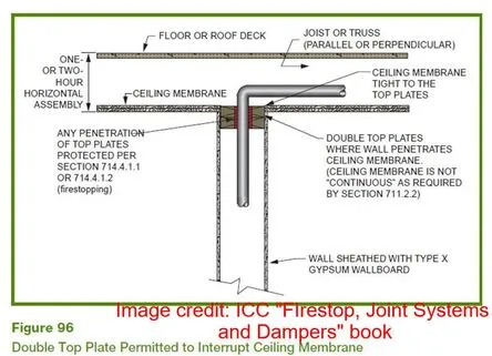
Recognizing the criticality of the ceiling membrane to the fire resistance of the entire floor/ceiling assembly, and of any interruptions to it, the 2015 IBC has the following requirement:
714.4.2 Membrane penetrations. Penetrations of membranes that are part of a horizontal assembly shall comply with Section 714.4.1.1 or 714.4.1.2. Where floor/ceiling assemblies are required to have a fire-resistance rating, recessed fixtures shall be installed such that the required fire resistance will not be reduced.
Exceptions:
1…
2…
7. The ceiling membrane of 1- and 2-hour fire-resistance-rated horizontal assemblies is permitted to be interrupted with the double wood top plate of a wall assembly that is sheathed with Type X gypsum wallboard, provided that all penetrating items through the double top plates are protected in accordance with Section 714.4.1.1 or 714.4.1.2 and the ceiling membrane is tight to the top plates.
To summarize, all penetrations of the top plate of the walls must be protected in accordance with the referenced code sections, which require that firestopping be installed as-tested, meaning as per a tested and listed penetration firestop system.
The IBC does contain marking requirements for fire walls, fire barriers, fire partitions, smoke barriers and smoke partitions. The requirements are contained in Section 703.7 of the 2013 IBC as follows:
“703.7 Marking and identification. Fire walls, fire barriers, fire partitions, smoke barriers and smoke partitions or any other wall required to have protected openings or penetrations shall be effectively and permanently identified with signs or stenciling. Such identification shall:
1. Be located in accessible concealed floor, floor-ceiling or attic spaces;
2. Be located within 15 feet (4572 mm ) of the end of each wall and at intervals not exceeding 30 feet (9144 mm) measured horizontally along the wall or partition; and
3. Include lettering not less than 3 inches (76 mm) in height with a minimum 3/8 inch (9.5 mm) stroke in a contrasting color incorporating the suggested wording.
“FIRE AND/OR SMOKE BARRIER—PROTECT ALL OPENINGS” or other wording.
Exception: Walls in Group R-2 occupancies that do not have a removable decorative ceiling allowing access to the concealed space.”
Individual penetrations are not required to be marked or identified by the Codes. However, many manufacturers and installers of Firestop Systems do provide Marking Labels designed to identify each of the Systems individually. The Firestop Contractors International Association (FCIA) also has requirements for Labeling and Marking of Individual systems that are used by Qualified Firestop Contractors (e.g. qualified via UL or FM). The Firestop Systems labels are recommended to be installed at each penetrating item, on the wall or floor, unless there are multiple firestop systems in the same area, with close proximity limiting access to the area for installation and readability of the identification system.
There are some distinct advantages to Labeling in this manner. These are discussed in the attached publication from FCIA.
The IFC has a publication that aims to clarify the IBC-mandated protection requirements and protection exemptions for recessed boxes. It can be downloaded free from this link:
Guide for Protection of Recessed Boxes in Fire-Rated Walls Using Firestop Putty Pads, Box Inserts, Cover Plate Gaskets and Endothermic Mats
UL has, over the years, issued various articles to address the confusion expressed by the Code Officials. Those publications can be downloaded from the following links:
UL Membrane Penetrations in Fire-Resistance Rated Walls
UL Question Corner
The IRC does not define the term “Combustible Construction”. However, the IBC does define Construction Types in varying degrees of “combustible” or “non-combustible” construction as follows:
602.2 Types I and II. Types I and II construction are those types of construction in which the building elements listed in Table 601 are of non-combustible materials, except as permitted in Section 603 and elsewhere in this code.
602.3 Type III. Type III construction is that type of construction in which the exterior walls are of noncombustible materials and the interior building elements are of any material permitted by this code. Fire-retardant-treated wood framing complying with Section 2303.2 shall be permitted within exterior wall assemblies of a 2-hour rating or less.
602.4 Type IV. Type IV construction (Heavy Timber, HT) is that type of construction in which the exterior walls are of noncombustible materials and the interior building elements are of solid or laminated wood without concealed spaces. The details of Type IV construction shall comply with the provisions of this section. Fire-retardant-treated wood framing complying with Section 2303.2 shall be permitted within exterior wall assemblies with a 2-hour rating or less. Minimum solid sawn nominal dimensions are required for structures built using Type IV construction (HT). For glued laminated members the equivalent net finished width and depths corresponding to the minimum nominal width and depths of solid sawn lumber are required as specified in Table 602.4.
602.5 Type V. Type V construction is that type of construction in which the structural elements, exterior walls and interior walls are of any materials permitted by this code.
In order for the construction to be considered “non-combustible”, it is not simply a matter of looking at the walls versus the floors, but rather, to look at the entire structure.
Having said that, while 302.11 of the 2012 IRC does refer to “combustible construction” as you indicated, R502.13 addresses Fireblocking in Wood Floors specifically. It states the following:
SECTION R502 – WOOD FLOOR FRAMING
R502.13 Fireblocking required. Fireblocking shall be provided in accordance with Section R302.11.
Because you are using Steel Wall Framing, you can apply Section R603 to the wall condition. That section does not mention the need for Fireblocking within the steel stud walls. In contrast, Section R602 does require Fireblocking for Wood Wall Framing.
While the IRC may appear to be somewhat inconsistent, Section R102 clearly states the following:
SECTION R102 – APPLICABILITY
R102.1 General. Where there is a conflict between a general requirement and a specific requirement, the specific requirement shall be applicable. Where, in any specific case, different sections of this code specify different materials, methods of construction or other requirements, the most restrictive shall govern.
In conclusion, based on IRC section R502, we would consider that Fireblocking is required in the wood floor. Similarly, based on R603, it does not appear that Fireblocking is required within the steel framed walls.
I am not aware of any instance where firestopping materials produced by different manufacturers (or the same manufacturer for that matter) have self-ignited when combined and in contact with one another. The inspector is referring to the fact that Manufacturers do not test their products together. Therefore, they cannot be expected to perform in a
All elements of a tested and rated firestop system, including the assembly into which the system is installed, constitute a specific and inseparable engineered unit that must be utilized as such. Firestop system designs are tested and listed by independent testing agencies such as Underwriters Laboratories, Inc. (UL), Underwriters Laboratories of Canada (ULC), Intertek, and South West Research Institute (SWRI). The specific elements of each design become integral to the listing. Manufacturers of tested systems do not test and list mixtures of products from different manufacturers in a single system, so that condition should never arise in a properly installed firestop system. Consequently, it is definitely true that compatibility between different manufacturer’s products is not tested by anyone, so no manufacturer can confirm that their products will work as designed and tested if two different manufacturer’s products are put into the same opening (i.e. therefore in contact with one another), or system.
While there are numerous UL (and cUL) Listings for stainless steel flexible gas pipe, we are not aware of any current listings for larger diameter ss pipes for the applications you describe. UL does have three listed systems using SS piping, C-AJ-1434, C-AJ-1504 and C-AJ-1553. Unfortunately, these are Nom 1/4 in. diam by 10 in. long “T” shaped vent tubes, or Nom 1 in. max, fabricated from stainless steel.
While almost all manufacturers of FS systems provide training for Contractors and Installers, there are currently no requirements in the ICC or NFPA Codes for FS system installers to be certified or qualified by either Manufacturers or Third Party Agencies such as UL or FM. While such training and qualification is clearly a “Best Practice”, it is not mandatory.
As you probably know, the IBC does include Special Inspection requirements for fire-resistant penetrations and joints in high-rise buildings, in buildings assigned to Risk Category III or IV or in fire areas containing Group R occupancies with an occupant load greater than 250. Special Inspections apply for through-penetrations, membrane penetration firestops, fire-resistant joint systems and perimeter fire barrier systems that are tested and listed in accordance with Sections 714 and 715 shall be in accordance with Section 1705.18. For additional information on special inspector qualifications see IFC document on special inspector qualifications.
The use of dissimilar materials, particularly piping materials, has become a very common practice. IBC 714.3.3 and 714.4.3 are intended to address this condition by effectively expressing the intent of the Code, which to ensure that the fire-resistance integrity of rated the walls and horizontal assemblies is maintained when they are penetrated.
The IBC, and the test Standards used to test firestop systems, are predicated on the assumption that the penetrating item is continuous through the fire compartment. As a result, once a penetration is firestopped at the floor or wall, there is no opportunity for fire to enter the adjacent areas either around, or through, the penetrating item. So the primary concern with noncombustible penetrating items connecting to combustible materials beyond the point of firestopping is the risk of the penetrant itself become a source of the breach in protection. Consequently, things like the method of coupling pipes together become critically important, as potentially, does the distance above the floor or away from a wall. The test methods specified by the IBC to evaluate firestop systems, UL 1479 and ASTM E814, evaluate the penetrating item up to a length of 3 ft beyond the fire-resistance rated wall or horizontal assembly.
The most common approach to address this condition is that manufacturers will test several pipe transitions in UL 1479 or ASTM E814 fire tests. The Listed systems will identify that transitions made beyond the point of the fire-resistance rated wall or horizontal assembly can be used to demonstrate that the fire-resistance integrity of rated the walls or horizontal assemblies is maintained. . It should also be noted that, up to the dimensions of the test specimens used in UL 1479 and ASTM E814, e.g. 36 inches, the firestop system and penetrant tested does demonstrate compliance with the intent of IBC 714.3.3 and 714.4.3 in regards to maintaining the integrity of the assembly in which they are installed. However, there are also cases where the transitions do not occur within the dimensions specified in the Listings, and furthermore, may occur beyond the normal dimensions used to test firestop systems in UL 1479 or ASTM E814. In those cases, because it would be impossible to test every single permutation of combustible pipe, noncombustible pipe, pipe diameters, distance of transition from assembly, and assembly penetrated, Engineering Judgments (EJ’s), can be developed to instruct a user how to firestop a penetration that involves pipe materials, diameters, and distances from the penetration different than that in the referenced, listed system(s). The general concepts used for evaluating transitions within the tested systems are then applied to the site conditions to determine whether the entire penetrant and firestop system will “demonstrate” that the transition can be made effectively.
It is also worthwhile to note that the 2015 edition of NFPA 101 also addresses this condition. It takes a slightly different approach, which is still consistent with the concepts identified above. It states:
8.3.5.5 Transitions.
8.3.5.5.1 Where piping penetrates a fire resistance–rated wall or floor assembly, combustible piping shall not connect to noncombustible piping within 36 in. (915 mm) of the firestop system or device without demonstration that the transition will not reduce the fire resistance rating, except in the case of previously approved installations.
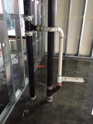
The approach used by NFPA 101, Life Safety Code, is essentially to limit transitions to being installed only beyond the 36 inch limit (which is consistent with the test Standards for through penetration firestops), unless the transitions have been tested within the first 36 inches beyond the unexposed surface of a horizontal assembly, or wall assembly. The corollary is that transitions that occur beyond the 36 inch dimension are considered to not detrimentally affect the fire-resistance rating of the assemblies in which they are installed.
When UL refers to penetrating items in a firestop system as being “rigidly supported”, what they mean is that none of the weight of the penetrating item(s) can bear upon the firestop products. Otherwise, the weight of those penetrants could disturb or completely dislodge the installed firestopping, especially during a fire exposure.
This information can be found in UL GuideInfo for listing category XHEZ: https://iq.ulprospector.com/en/profile?e=212159
Quoting from there:
“Where the individual system specifies the penetrating item is to be rigidly supported on both sides of wall or floor, the support system should be designed based upon the premise the firestop system provides no support.”
Penetrating items should be supported as per the governing codes that pertain to them, such as the International Mechanical Code, International Plumbing Code, or National Electrical Code.
According to the guidance provided in UL’s Firestop and Joint Application Guide: “a minimum compression of 25% would be an example of tightly/firmly packed.”
